

Tech Tip: Exhaust Ventilation Modeling in eQuest
Relevant 90.1 Baseline Rules
G3.1.2.4 Fan System Operation: Supply and return fans shall operate continuously whenever spaces are occupied and shall be cycled to meet heating and cooling loads during unoccupied hours.
G3.1.2.9 System Fan Power: System fan electrical power for supply, return, exhaust, and relief for Systems 1 and 2:
Pfan = CFMs × 0.3
G3.1.2.5 Ventilation: Minimum ventilation system outdoor air intake flow shall be the same for the proposed design and baseline building design.
Exception to G3.1.2.5-3. Where the minimum outdoor air intake flow in the proposed design is provided in excess of the amount required by the building code or the rating authority, the baseline building design shall be modeled to reflect the greater of that required by either the rating authority or the building code and will be less than the proposed design.
Example 1: Continuous Exhaust + Trickle Vents
Proposed In-Unit HVAC:
PTACs that cycle with load to provide heating and cooling
PTAC fan power is 0.2 W/CFM, 2-speed fan
Continuous 100 CFM exhaust from kitchens and bathrooms via rooftop exhaust fan (EF) @ 0.4 W/CFM
Make-up air through trickle vents
Proposed Corridor HVAC
Roof-top unit (RTU) provides heating, cooling and ventilation to corridors
0.7 W/CFM RTU supply fan
Exhaust and make-up ventilation rates meet applicable codes (i.e. no over-ventilation penalty)
Baseline In-Unit PTAC Fan Power and Control
Baseline In-Unit PTAC Sizing


Baseline In-Unit PTAC Ventilation Rate
Set OA Air Flow (cfm) to 0.01 to force PTAC to run continuously (eQUEST work-around)
Enter exhaust as specified
Enter 0 W/CFM exhaust, since we allocated the full baseline fan power to PTAC supply fan (an acceptable simplification with negligible impact on results)
Set “Source” as shown, to indicate that make-up air is provided via balanced infiltration

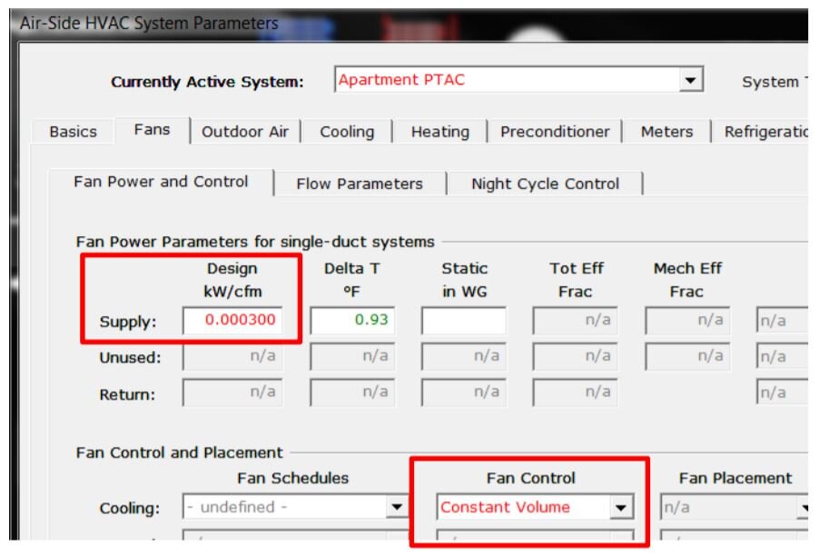
Proposed Design: PTAC Fan Power and Control
Set PTAC fan power and control as specified

Proposed Design: In-Unit Exhaust Fans
Set exhaust fan power as specified
Set PTAC supply air flow to 0, to allow PTAC cycle with load

Proposed Design: Corridor RTU
Enter RTU fan power as specified

Example 2: Continuous Exhaust + Mechanical Supply Ventilation
Please note: Example 2 is based on eQuest build 7173 (DOE2.2).
Proposed In-Unit HVAC:
PTACs that cycle with load to provide heating and cooling
PTAC fan power is 0.2 W/CFM, 2-speed fan
Continuous 100 CFM exhaust from kitchens and bathrooms via rooftop exhaust fan (EF) @ 0.4 W/CFM
Make-up air through trickle vents
Proposed Corridor HVAC
Roof-top unit (RTU) provides heating, cooling and ventilation to corridors
0.7 W/CFM RTU supply fan
ducted to supply 60 CFM make-up air to each apartment
Exhaust and make-up ventilation rates meet applicable codes (i.e. no over-ventilation penalty)
Baseline HVAC
Same as above in Example 1, except:
In-unit supply CFM should be modeled as 60 OA CFM
Model RTU as PSZ system type instead of PTAC, to simplify modeling proposed design


Proposed In-Unit Systems
Enter in-unit exhaust fans, PTAC fans, and corridor RTU fans the same as in Example 1 above

RTU Make-up to Apartments
Reference the corridor RTU as the unit that supplies mechanical ventilation to apartments.
RTU OA CFM must be increased to include in-unit ventilation
Floors 2-10 each have 8 apartments; in order to supply 60 CFM OA ducted to each apartment, the corridor ventilation on these floors must be increased by 60 x 8 = 480 CFM
First floor has 4 apartments, so 4*60=240 CFM must be added to the
corresponding Thermal Zone (Parameter #3 below, not shown)


Impact on Energy Consumption (Example 1 & 2)
Similar changes in energy use between the baseline and proposed for both examples
Ventilation (fan) energy is the area of greatest impact
Savings strongly depend on efficient fan system design
Example 2 has slightly higher overall energy use for both the baseline and proposed design
Note: The examples demonstrate methods for modeling different ventilation designs. Additional inputs, such as specified supply flow rates, heating and cooling capacities for RTU and PTACs will be required to meet 90.1 requirements.
